The following guide was written by Brett Rogers for a fellow FSC member who was having problems with her Rolleicord. He kindly gave us us permission to this share this on our website, we are grateful for that and this incredible resource, thank you Brett!
Rolleicord V Sticking Slow Shutter Speeds—How To Fix It
The Rolleicord V is my favourite Rolleicord model of all. I find it handles the best. I’ve worked on several examples of them. It’s not so hard to reach the shutter and escapement of one, (it will be the escapement that’s causing the slow speeds to stick). This guide was written in reference to the Rolleicord V model, but it’s equally relevant to the Va and Vb Rolleicords also. The general principles of how the speed escapement works apply to most Compur shutters.
First, the knob for the cocking lever has to come off. Deft use of pliers, tweezers and screwdrivers is required to detach its round fastening nut—it’s a bit fiddly. Once you’ve peeled the leatherette back at the four corners and unscrewed the fastening ring for the PC terminal locking clip (use a small piece of rubber to avoid marking it) you can remove the fixing screw for the bayonet plate at each corner. There are four more screws—these retain the actual lens board which you do *not* need to remove—leave those well alone. The bayonet plate then slips up and off the viewing lens and it will clear the end of the cocking lever if you tease it up at 90 degrees and slide it along the slot. Then you may unscrew the front lens group if you haven’t already done that and bingo, there is the front of the shutter housing. The picture below is of a Rolleicord Vb but it’s the same process.

A set screw secures the black retaining ring for the front of the shutter. Set the shutter speed to “B” (note the dot and dashes stamped on front denoting each speed) and, after removing the set screw, unscrew the retaining ring.
If it’s your first time inside a Synchro Compur, taking plenty of reference photos as you go is a good idea. What you need to clean (the speed escapement) is not hard to access. But its end lever does need to be meshed back in correctly, on re-installation. You also need to note the mesh between the cocking rack teeth and the main spring pinion (as we’ll see further on) since the shutter might cock and fire OK, if you’re off a tooth, but will also misbehave.
There are a number of other parts within, but these will not fly out at you when you take the front rings off. But they’re also not all that hard to inadvertently dislodge, and you may not realise you’ve done that until later when it won’t work correctly. Here’s the view of a Rolleicord VB shutter that’s nearly identical to the one fitted to a V. You’ll note the cocking ring circling the inner shutter diameter, and which of its teeth mates to its counterpart on the main spring pinion. Don’t worry; there are better diagrams from the manual further on than these images.

Take plenty of photos at each stage—close up, detailed ones. Sometimes, these can actually be better than looking at the shutter. A digital bridge or compact camera with a decent macro mode can easily reveal details of tiny parts you or I might struggle to see with the naked eye.
Below is a link to my Dropbox that will retrieve a copy of the factory Compur repair manual.
https://www.dropbox.com/s/1ckk1zdgktqrj2d/Compur%20Factory%20Shutter%20Repair%20Manual.pdf?dl=0
This document is the official factory manual published by F. Deckel, but it’s an arcane document that offers few clues about it should be interpreted. Having pored over it for many hours I’ve got my head around it, so let me make it a bit easier for you.
Deckel made many, many versions of the Compur shutter for all manner of 35mm, medium format, or large format cameras or their lenses: SLRs; rangefinders; TLRs; large format lens shutters; Hasselblad lenses; you name it. So first, you need to check the reference tables in Section 3, to work out exactly which mechanism is the one installed in the camera in question.
You’ll find the Rolleicord V on page 41 of the pdf. The same shutter was used in the Va and earlier Vb models. Late Vbs dropped M sync and had X sync and self timer only, not MXV like previous ones.
The basic shutter number is CN-1110-000. This is not completely identical externally to the item fitted to your Rolleicord V. The details of how the cocking ring is actuated and the levers for the shutter and aperture drive for starters, differ, but this is of little consequence. The actual shutter fitted would be special shutter number CS-1110-231a which is not illustrated, but that’s OK—the internals are the same. Hence if you need to refer to exploded diagrams of the Rolleicord V shutter internals, the plate numbers for CN-110-000-in Section 4 (beginning on page 50) are fine.

If you’re wondering what you can expect to find once you have removed the bayonet plate from your Rollei, the top picture on page 59 is closer to it.

Forget the ring with shutter speeds printed on it above. To begin accessing the internals of the Cord V (after having unscrewed the front lens group, of course) you’d remove the small locking screw visible, which enables you to then unscrew the black securing ring with the three cut outs. This is what actually holds the front rings onto the shutter housing. The inner ring beneath it is pretty much identical (or identical) to what is in the V shutter. The outer ring that fits under this is the same as well, except that, being hidden beneath the cover of the Rolleicord it won’t have “Synchro Compur” engraved into it, just a stamped, unmarked, scale for each speed from B to 1/500.
That ring couples to the speed control ring underneath it (partially visible above, with all the slots stamped out of it). Staying on the this diagram for a moment, the shutter ring with the printed speeds above is not needed on the Rolleicord V, obviously, as its speed control ring is driven via the external setting lever—hence, under those two initial rings, you’ll just find the cam ring.
Getting back to page 50 of the manual, the external rings and actuating levers on the top image don’t look a lot like the V shutter, but the bottom image (shown below) shows the top view of the speed control cam, as it will appear with the retaining ring and the inner and outer front rings removed (minus the external setting levers for this particular camera, of course).

Looking at the above image, you can see the slots that drive various pins to engage or disengage the escapement or its retard pallet (I.e. the slow speeds) or to provide the Bulb override (via the tab on the pallet control).
The escapement works on a combination of inertia and retard (I.e. drag). At intermediate speeds the retard function (the pallet and star wheel that give you the familiar “bzzzzzzzz” as it runs off) is not engaged. However the escapement is still engaged and as the shutter releases it will freewheel (so to speak). I.e. it unwinds rapidly but the mass of the gear train still creates a smaller delay that provides the intermediate speeds. We’ll look at the escapement in a moment. But know that at 1/500 setting, the control pins completely isolate the escapement altogether—when the shutter fires on 1/500 it’s running straight off the power of the main spring without any interruption.
The slots in the speed control ring (they’re a sort of profiled cam system) are what switch these in or out. If you take a look at the slot on the right of the image around the clock from about 1 to 4 o’clock this engages the escapement pins including the retard function. You’ll see a small flat around 4pm. This is for one second. Looking up the picture the slot is stepped and curves outwards (to 1/2 second, the pallet runs half as long, based on how far the cam slot locates the pin). Then it steps up again to ¼ second, 1/8, before the pin to disable the retard pallet comes into play, hence, the slot curves inwards sharply towards the centre of the shutter (which, with the pallet locked out, is 1/15). And so on.
Let’s look at the escapement controlled by the cam ring. You’ll find a good image of it, complete, (part 300) at the top of page 54 (reproduced below). Its two retaining screws, 304, and 323, are the ones you’ll have to unfasten, to get it out for cleaning. But first, take some feeler gauge measurements of its installed position relative to the shutter housing, before you remove it. If you’re very lucky, when you re-install it you might get the speeds this way. But it’s very fussy about its precise location, so, odds are high that it will need to be finessed into correct position. It’s usually a little quicker than dropping it in and starting from scratch though.

The image below shows the individual escapement parts. Unhelpfully, it’s illustrated 180 degrees about from the previous diagram, (note the curve of the plates, in the two images). You don’t want to strip it right down—so please don’t, as it’s not necessary, to clean and lube it, and if you do you most likely won’t get it correctly re-assembled.

There are a few things worth pointing out above. Parts 341 and 305 each have a sort of peg or pin sticking up and 319 has more of a tab also pointing in the same direction. These are some of the parts the slots in that speed control ring actually push in or out to give you the speeds. By now, this is all beginning to make sense, I hope.
Parts 316 and 321 are of special importance. 316 is the last gear in the gear train and is driven by spring power (when engaged) via the small gear at the top. The larger, lower gear has teeth that have a different profile to all others. They don’t mesh with any gear. It’s the “star wheel”. These specially profiled teeth run against the edge of part number 321—the pallet. They’re what create the drag required to slow the escapement right down for the 1s to 1/8 times. Whether you get 1 or 1/8, or a speed in between depends on how far the arming lever compresses the spring, and thus, how far it runs off when the shutter trips. Of course, the amount of run off, and, hence, the time, is determined by what speed the control ring is set to, and where the control pins are positioned.
The above gets to the heart of why a Compur may have sticking slow speeds. It’s quite likely the shutter blades may benefit from the removal of accumulated evaporated lubricant residue (which occurs as the liquid and solid components of greases separate or oils evaporate). I would always recommend swabbing clean the shutter and aperture blades, if you’ve gone to the trouble of opening up the front of the camera and shutter housing—but the slow speeds, specifically, will probably be malfunctioning because the escapement is stalling.
Depending on how a particular camera has been used and stored, certainly, the ingress of excessive dust can contribute to an escapement sticking. But even a Rollei that’s never been used since manufacture 60-odd years ago, will probably misbehave today if not serviced. The original lubricants were either mineral based or organic, and by now they’ll be too deteriorated to keep the escapement running smoothly. The result is that stuttering sound many of us are familiar with, as the escapement spring does its best to drive the gears against the additional resistance created by accumulated debris and congealed lubricants, but stalls, because it’s not powerful enough (and is not meant to be).
Once you’ve got the escapement out, cleaning it involves immersing it in a suitable solvent (I usually use lighter fluid, basically, naphtha) and manually operating it until it’s clean and runs off freely.
Keep your wits about you as you clean it. The first time I cleaned one, I had it all back together in the shutter, and was feeling very pleased with myself until I found I’d lost the slow speeds. It turned out that, in the course of cleaning the escapement, I’d inadvertently dislodged spring 320, (which presses the pallet up against the star wheel) off its perch. It’s so small, I could barely see it (I didn’t have the repair manual and its diagrams, at that time). An hour later, I finally spotted it, re-set it, and got the escapement positioned again. Don’t do what I did!
After cleaning the escapement, you’ll want to apply a speck of suitable oil to the shafts of the gears, where they run in the top and bottom plates, and also to the teeth of the star wheel. Personally, I have had good results from Moebius 8000/4 in a number of different Synchro Compur shutter escapements. This should get the slow speeds running off like new again, at which point, you’re ready to reinstall the escapement into the shutter.
Page 58 in the pdf shows the escapement installed back into the housing, ready for positioning (see image below). Understand that it is not just the location of the escapement relative to the inner or outer shutter housing that is critical. To get your speeds good you’ll need to also position it in the correct rotation “around the clock”. I.e... Broadly, as shown in the picture below, left/right and up/down. Proper alignment in all directions is critical to restoring the correct times.

You will know it’s correctly positioned (or getting close), when the 1/15 time sounds good. It’s not hard to get one second, 1/2, 1/4 etc OK—one second is typically on maximum retard run off, anyway. But if the escapement positioning is not spot-on, 1/15 will very probably sound (and be) the same as 1/30. When correctly set, there should be a very clear difference between those two, and if you get them right, all the other speeds ought to fall into place. After years of working on various cameras with Compur shutters, I can tell by ear (duration, pitch etc) pretty well, whether one is good. Naturally, my ear is not as accurate as a modern electronic tester—but—accurate enough to get great results with transparency? Definitely. These days I have various electronic testers of differing vintage and sophistication, but, my ear still guides me right into the ballpark. How you check the speeds is up to you—there are phone apps and dedicated electronic testers of various ages and sophistication.
There are some instructions in the manual about positioning the escapement and setting the times. In conjunction with figures 1 to 5 on page 58, you’ll find the relevant text on pdf pages 133 to 134. Excerpts below:
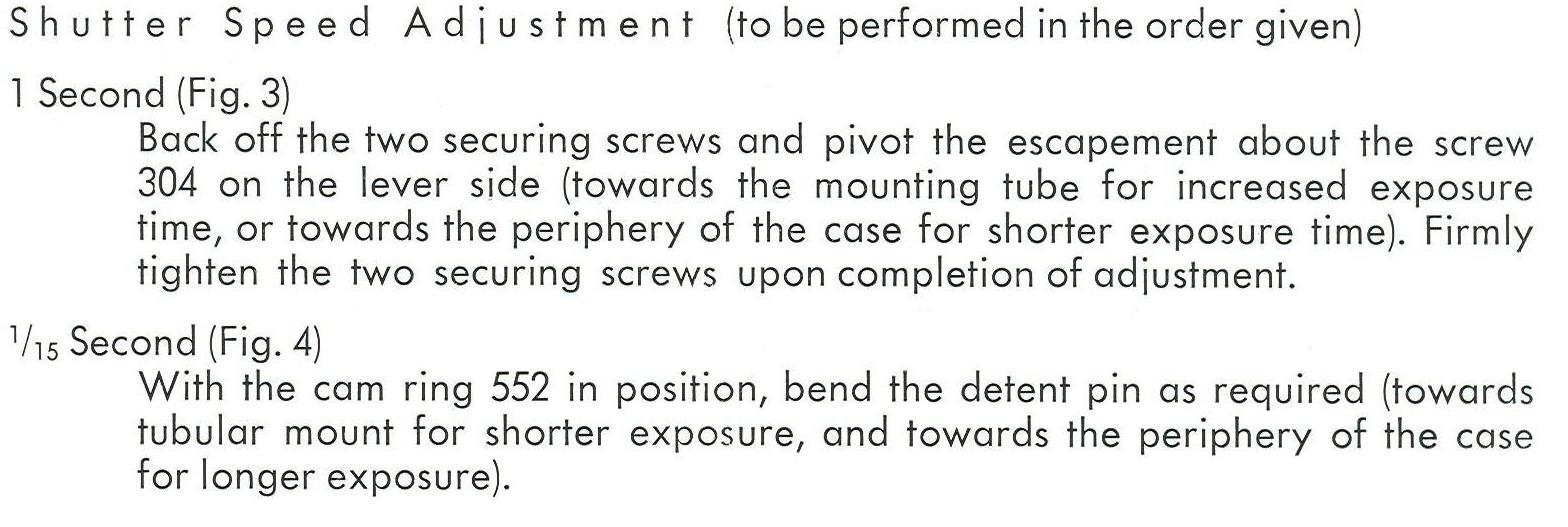
My remarks about the above are: whilst it’s fine, in theory, to bend the escapement pins to achieve the correct times, the pins don’t bend much before they snap. And if an escapement came out of a shutter that was delivering reasonably accurate times—well, was capable of, anyway, before it needed cleaning, then—it should be possible to replace the escapement in the same position it was removed and get the times good, without bending the pins. After all, you’re not replacing an escapement with a new part—merely re-installing a previously adjusted one. If your shutter speeds aren’t all present and correct, keep checking the escapement position. It probably still needs some correction—bending the pins should be the last resort. And if you don’t have the speeds in the ballpark, any adjustments needed are likely to be outside the scope of that available by bending the pins in the first place. It’s for fine tuning them, not for getting them approximately right.
Allowing for the tolerances given above, and the age of the mechanism, don’t be too pedantic about absolute accuracy. As the manual states, 15-20% was acceptable when these shutters were brand new, so a consistent 20-30% is pretty reasonable 60 years later. Such deviation from nominal is of little consequence when using negative films, and, providing your shutter is running consistently, it’s easily adjusted for with aperture if you want to shoot some slide.
There is another escapement inside this shutter—that which provides the self timer delay. It’s similar to the speed escapement in principle, only less complex. It has no inertia function and is a simple retard escapement. Whenever it runs the pallet and star wheel are always engaged, because it’s a single speed type that runs for a longer duration.
All the points mentioned above about gear trains or pallets stalling are just as relevant to the timer escapement. The same issues cause the same sorts of problems. Personally, unless the shutter in question is being stripped right down I wouldn’t bother removing the timer. A little lighter fluid applied to its star wheel and gears, one small drop at a time, and some repeated firing, will usually see it running off happily. As with the speed escapement, a speck of oil to the star wheel and gear pinions will keep it that way for years.
There are a few other points worth investing a bit of time in. I find a speck of oil on the shaft of the main spring gear pinion is prudent, having previously had to address this point. It’s part 517 in the following image (from page 51 of the pdf). Beneath it is 515, the main spring, which is what makes the whole plot run. Part 514, beneath that, trips the levers that open and close the shutter blades and arms the speed escapement. It will run dry if it has to—but a speck of moly grease applied with a toothpick to the edges of its protrusions, is one of those little tricks that will help the shutter to cock just a bit more smoothly.
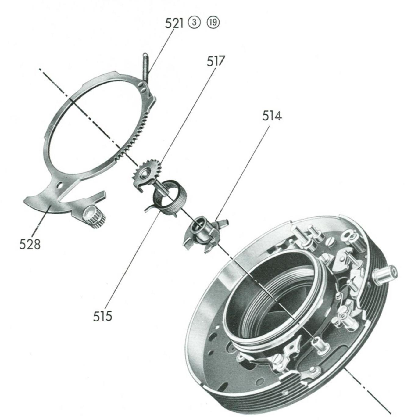

Note that the correct mesh of the main spring pinion to the cocking ring is the first tooth of the pinion to the first recess in the ring. It’s shown above (uncocked). If you get the mesh out in either direction it may not cock or may be prone to self releasing part way through the cocking cycle.
I like to run a trace of moly grease around the circumferences of the rings including the cocking ring before it goes back on the housing, as well as the cam ring and shutter control ring—it helps to make these rotate easily without binding or resistance.
I’ll usually place a trace on the edges of the cam ring slots for the same reason. It won’t make much difference if the shutter is released, but, if you change the speeds with the shutter cocked and Egg the escapement pins are under some tension, it will help make the speed lever smoother to actuate, and this may be important if, like me, you value having a Rollei that handles and feels like a Rollei should.
There are several thread holes for the locking screw tapped into the inner front ring. In conjunction with the three cut outs in the black securing ring, this makes for quite a number of possible positions you can lock it to, around the clock. By all means, make a note of the thread turns and installed position when you initially remove it, and replicate this, if you can. But don’t stress too much. It’s essential that the ring is fastened tightly enough to keep the front components snugly in place against the top of the housing. If it’s too loose, one or more control pins might easily pop out of the correct slot. Naturally you don’t want that.
But it’s also very easy to over-tighten the retaining ring, and, whilst the shutter will probably function correctly, it will be more difficult, than it should be, to adjust the speeds, the control pins and cam ring will wear too quickly, and the shutter lever will be stiff and unpleasant to move. Perhaps the best advice is to actuate the speed ring a few times before opening the shutter up, and, try to replicate the same sort of feel it had before you removed it. Firmer rather than looser, is the lesser of two evils—but only within reason. Easy does it.
After carefully checking all speeds and the timer a number of times you can re-fit the bayonet plate. You’ll want to ensure the shutter control ring is set to B and that the B setting is centred in its window within the plate, likewise, the aperture control pin and its control fork on the end of the operating lever should be aligned. Flash sync/timer should also be set to mate sweetly as should the double exposure switch (which, from memory, should probably be set to “off” as you slide the cover on). Similarly, the sync/timer switch has its sweet spot that will help its fork engage the pin. Don’t be afraid to arm the self timer and set the switch accordingly, if it proves recalcitrant—sometimes this can help.
It can be fiddly to keep all these things in the right positions simultaneously, as you lower the plate onto the lens board. If you’ve not done this before, expect to have to repeat it several times before it’s correct. A little wiggling of the plate as it’s brought home can help the controls to mesh. But don’t force it. When they’re correctly mated, the plate will align perfectly with the lens board. If it fails to fully seat, or sits unevenly, something isn’t engaged correctly. Patience will get you there. Secure the board fastening screws, re-fit the knob for the cocking lever and PC socket lock, and glue on the leatherette (I use a generic contact adhesive that hangs on well but can be pried loose, if needed), and it’s time for you to load a film.

Left to Right: Two Rolleicord V models; a Rolleicord Va and; a Rolleicord Vb.
CONNECT
Brett Rogers photographs with 35mm, medium format and large format film. Imaging genres include landscape, architectural, concert, and automotive photography. Brett uses an eclectic range of classic camera equipment from ALPA to Zenit, much of which was found cheaply in non-working condition and repaired by him. He lives on a small acreage in southern Tasmania with his spouse, son, four Border Collies, three cats, a menagerie of poultry, native fauna species, and a peacock.
(Links)
Facebook
https://www.facebook.com/tasmania.film.photography/
Flickr
https://www.flickr.com/people/43224475@N08/